Ta-done! (Almost.) My bitbeam-based CNC machine (aka “bitbeambot“) is now mechanics-complete. The physical structure is done, and now it’s time to focus on the electronics and software.
The galactic premiere and live demo of the bitbeambot playing Angry Birds on an iPhone will be this Sunday, October 2 at the Jenkins User Conference in San Francisco. Hope to see you there!
I just submitted (5 minutes before the deadline! Phew!) my entry to the Open Hardware scholarship contest. Here’s the description I included in the contest entry:
Project Description: Bitbeam is an experiment to combine my two favorite prototyping tools: balsa/basswood and Lego. The idea is to miniaturize grid beam and make it Lego Technic compatible.
As with Lego, you can build anything with bitbeam. My first bitbeam project is to build a CNC machine, but with a twist. My background is in software testing, so I’m building a machine out of bitbeam that can test applications on actual mobile hardware, using the Selenium automation API.
Comments welcome!
[Update: Voting is over. Results are at OHSummit. Bitbeam didn’t win. 😦 But thank you to all who voted! 🙂 ]
Time for an update of the goings-on in the Bitbeam Basement.
Last week, I purchased some stepper motors from Jameco (Part #: 155460). I went with bipolar instead of unipolar based on what I read on the RepRap wiki page about steppers — bipolar steppers are used in newer RepRap machine designs. I figured what’s good for RepRap would be good for me, since I didn’t have an opinion either way.
Next step was to wire up the motor. Here’s a trick: if you’re searching for concise, correct, easy-to-read instructions on how to create a simple circuit, always append the word “Arduino” to your Google search. It’s similar to searching for Linux related things — for the best docs, append the word “Ubuntu” to your search — beginner friendly technology projects always have the best docs! It also helps to actually use Arduino and Ubuntu, too! The Arduino bipolar stepper circuit shows how to use an L293D or SN754410NE chip (commonly called “H-bridge”) to drive the stepper. Very cool! I knew those were handy for DC motors, but didn’t realize they could be used for steppers, too. I happened to have lots of H-bridges around for another project. If you want to pick up some yourself, again Jameco is your friend. (Part #: 1341966)
After wiring-up, I launched the Arduino IDE and opened the stepper example. (Menu path: File->Examples->stepper->stepper_oneRevolution). The built-in library of ready-to-use real world example code is another reason why the Arduino project is so wonderful work with. Thanks also goes to Tom Igoe, who wrote the original version of the code and docs that made their way into the Arduino IDE and website.
With the code ready, and the basic H-bridge good to go, there was one more task to confirm– did I connect the stepper motor’s 4 wires to the H-bridge in the right sequence? Only after I created the above video, did I realize the online data sheet (PDF) shows the correct wiring diagram. I went the brute force way, and just re-arranged the 4 wires while the circuit was running on the Arduino until the axle was rotating properly in both directions. If you get the wiring sequence wrong, the stepper’s axle will mostly just jitter in place, rotating erratically. I had a sense that if I got the wiring wrong on the first try, nothing bad would happen (e.g. I wouldn’t likely kill the motor or the H-bridge chip), so I didn’t feel too guilty just plugging it in and seeing what happens. It’s a fine line knowing when to do precisely the right thing the first time, and when to just say “Oh, forget it. Let’s turn it on, and see what happens.”
The almost awesome part about these specific steppers is that the mounting holes are 31 mm apart from each other. Since bitbeam holes are 8 mm apart, a length of 5 BUs (Bitbeam Units) is 32 mm, which might work with these motors. I took a chance that the motors would mount as-is directly to a bitbeam. With a little bit of wiggle, it works. That’s why I said “almost awesome”. A stepper with mounting holes 32 mm would be perfect, but 31 is close enough. Lastly, I bought some machine screws from Small Parts to mount the motors to the bitbeams. (Part #: B000NHVPW2) (M3, 10mm long, Zinc Plated Steel Machine Screw, Pan Head, Phillips Drive.)
That’s it for now. The next post will show the stepper motor connected up (screwed up?) with some bitbeams driving the X-stage of an eventual Bitbeam CNC machine.
By default, OpenSCAD’s built-in circle and cylinder functions are fine. However, for small circles or cylinders with a radius of less than 3mm, the result doesn’t look much like a circle at all. This is how a newbie would code this in OpenSCAD.
// Typical small circlecircle(r=2.4);
And here’s the result – an octagon!?
The solution is to create a circle with a large radius, then scale it down to the size I want. My trick is to use a radius 10 times larger than I need, then use the scale function to reduce it to 10% of its original size.
// High-precision small circlescale([.1,.1])circle(r=24);
And the new, better, non-octagon-y result:
Why does this matter? Bitbeam requires a Lego Technic compatible through-hole radius of 2.4 mm. If I used the default octagon-producing output, and sent it to the laser cutter, round axles, dowels, or bolts would not have fit in the hole. My first remedy was to draw a circle in Inkscape, export to DXF, then use OpenSCAD’s linear_extrude function to import my circle and render. DXF-to-OpenSCAD is usually awesome and is featured prominently on the OpenSCAD home page. However, I’ve thankfully realized it’s total overkill for my simple small-radius circle. Trying to figure out how to create a circle in Inkscape in an OpenSCAD-compatible way was surprisingly complicated and tedius. Credit goes, though, to Nudel for posting an excellent and detailed Inkscape to OpenSCAD dxf tutorial. I will definely use that tutorial in the future for more sophisicated designs.
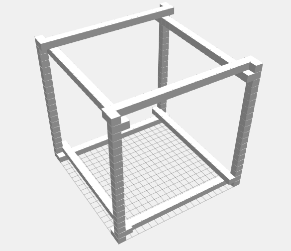
There were no nuts or bolts involved, and it assembles in a few minutes! It could use a couple of cross braces for stability, and I could upgrade it with 10-32 threaded nuts and bolts, but it’s fine for now just sitting there looking pretty on my desk.
This feels like Philosophy 101 and Plato’s Theory of Forms. The ideal cube on the left, a material cube on the right. (Does that make the MacBook the Cave? Okay, now I’ve confused myself.)
OpenSCAD is an excellent prototyping tool for creating 3D and 2D designs. OpenSCAD’s killer feature is parametric design. With a few simple shapes and a short script, you can create intricate designs that would have taken hours to create manually in a traditional CAD program.
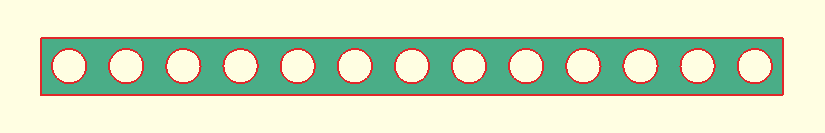
Of course, Bitbeam is not that intricate. It’s just a beam with holes — a “holey poley“. However, getting those holes perfectly placed and sized correctly is tedius to do manually.
Most OpenSCAD tutorials focus on its ability to create 3D designs that you can use in a 3D printer, like a MakerBot Thing-O-Matic. But I’m not using a 3D printer to create bitbeams. I only need a laser cutter, which means I only need 2D output. I’m using OpenSCAD for its ability to crank out variations of bitbeams in different lengths, so I can quickly create a laser-able “kit” of beams.
Below you’ll find the OpenSCAD source file I use to create my beams. It depends on a DXF file called “circle-4.8.dxf”. The source for the DXF file is included in the Gist. [Update: I figured out how to draw the circles without requiring a DXF file. (It’s a long story.)] It’s all MIT licensed. (Yeah, OSHW!)
Now that I have a basic beam defined in code, I can use the “beam” module to create various kits. For some designs I’m working on, I’ll need lots of long and short beams. Here’s an OpenSCAD file I used to bang out a bunch of beams in many different sizes.
Over the weekend, I watched my two sons play with the existing batch of Bitbeam beams. They kept trying to connect the beams to their existing Lego bricks, but couldn’t, since the Bitbeam’s through holes were too small. With that wee bit of customer development now simmering in my brain, it’s time to do a new design experiment — make the holes bigger!
I’ve upped the current hole size from 1/8 inch to 4.8mm — the exact width of a Technic through hole. Since I’m working with basswood here, and not the usual ABS plastic that Lego is made from, I was worried that these larger holes would be too close to the edge and make the beams too fragile. But so far, it’s looking good.
I should post my design files and start talking about the dev tool chain. (Short version: OpenSCAD -> Export to DXF -> Walk over to TechShop SF -> Import to CorelDRAW -> Cut!) Longer version will come in the future posts.
Here’s a prototype X-axis for a Bitbeam-based CNC machine. Okay, it’s pretty far from being fully armed and operational, but I hope you can see where this is going.
Bitbeam is an experiment to combine my two favorite prototyping tools: balsa/basswood and Lego. The idea is to miniaturize GridBeam and make it Lego Technic compatible.
Bitbeam height and width is 5/16 inches, and each hole is 8mm apart — just like Lego Technic. For the moment, the hole size is 1/8, slightly smaller than a Technic hole, BUT an 1/8 inch axle fits perfectly into Technic gears and bushings. (I might change this, though, by making the hole size bigger to be compatible wth Lego axles.) The hole size is 4.8 mm wide, also just like Lego Technic. I recently changed the hole size from 1/8 inch to 4.8 mm.
The advantage of building your own Bitbeam parts over Lego is that 1) the materials are cheaper, 2) I can make parts in sizes that Lego doesn’t make, and 3) playing with lasers is fun!This video is from some of my first laser cutting experiments at TechShop San Francisco in July, 2011. (Background voices in this video are from the TechShop’s Laser Cutting SBU instructor giving a class on one of the other lasers.)