OpenSCAD is an excellent prototyping tool for creating 3D and 2D designs. OpenSCAD’s killer feature is parametric design. With a few simple shapes and a short script, you can create intricate designs that would have taken hours to create manually in a traditional CAD program.
Of course, Bitbeam is not that intricate. It’s just a beam with holes — a “holey poley“. However, getting those holes perfectly placed and sized correctly is tedius to do manually.
Most OpenSCAD tutorials focus on its ability to create 3D designs that you can use in a 3D printer, like a MakerBot Thing-O-Matic. But I’m not using a 3D printer to create bitbeams. I only need a laser cutter, which means I only need 2D output. I’m using OpenSCAD for its ability to crank out variations of bitbeams in different lengths, so I can quickly create a laser-able “kit” of beams.
Below you’ll find the OpenSCAD source file I use to create my beams. It depends on a DXF file called “circle-4.8.dxf”. The source for the DXF file is included in the Gist. [Update: I figured out how to draw the circles without requiring a DXF file. (It’s a long story.)] It’s all MIT licensed. (Yeah, OSHW!)
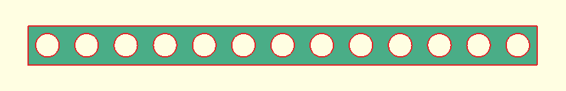
Now that I have a basic beam defined in code, I can use the “beam” module to create various kits. For some designs I’m working on, I’ll need lots of long and short beams. Here’s an OpenSCAD file I used to bang out a bunch of beams in many different sizes.
Which will produce this output:


Hi Jason,I’ve been meaning to ask you about your cut pattern. There is a lot of waste in cutting your bitbeams separately, with spaces in between. It seems to me you could get the same effect, with a lot less waste, by laying out your beams contiguously and then laser cutting them in this order:1. Cut all the holes. Your solid sheet of stock hold everything in place.2. Make the end cuts on all your sticks EXCEPT the 4 corner sticks. The sides of all the sticks are still connected, so you still have a sheet of connected pieces that won’t shift around.3. Starting at one side of your work piece with the outermost cut, make the lengthwise cuts that separate the beams from each other. In your diagram above, you would first make the cut at the top of the sheet, separating the top row of beams from your substrate. Next you would make the cut that separates the top row from the row below it. Your connected corners from step 2 will keep the uncut part of the substrate from moving around.4. Make the 4 remaining end cuts.Unless I’ve missed something crucial about laser cutting, by cutting in this sequence you should be able to create a solid sheet of accurate bitbeams, with your only waste the thin strips of wood along the perimeter of your workpiece.To further reduce waste, lay out bitbeams on every bit of space on your workpiece. If you’ve got space left over at the end, cut 1- or 2-hole beams. 1-hole and 2-hole beams are useful as spacers once you start using connectors long enough to connect 3 beams. Which I think you will want to do, because with beams this tiny, creating trusses will make your projects a lot more rigid.HTHJoy LivingwellGridbeamSolutions.com